You are here: Home » Blogs » Understanding Variable Frequency Drives: Key Benefits for Industrial Applications
Understanding Variable Frequency Drives: Key Benefits for Industrial Applications
Views: 0 Author: Site Editor Publish Time: 2026-07-21 Origin: Site
Industrial electric motors consume a massive portion of global energy resources. Running fixed-speed applications at continuous full capacity creates a severe energy drain. Traditional Direct-on-Line (DOL) motor starting and mechanical flow control methods, such as throttling valves and dampers, cause operational inefficiencies. They also lead to excessive mechanical wear and high utility demands. Facilities can no longer afford to waste power by running motors at full speed only to restrict their output mechanically.
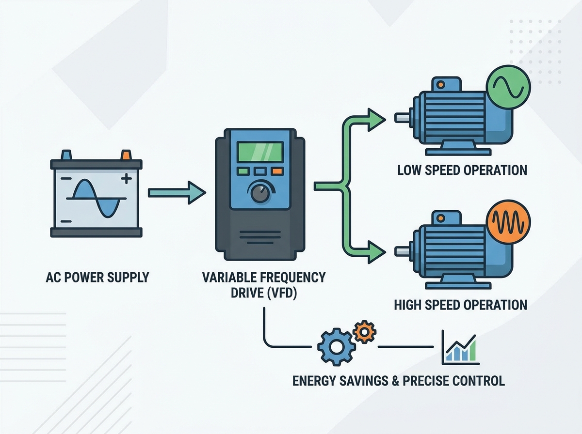
A Variable Frequency Drive serves as the definitive solution for aligning motor speed with actual process demand. This technology shifts the focus from basic functionality to strategic energy management. It reduces carbon footprints and improves overall equipment lifecycle management. By controlling the electrical input to the motor, operators gain precise control over mechanical output. You will learn how these drives operate, their core operational benefits, and how to navigate implementation realities to protect your industrial systems.
Energy ROI: Implementing a VFD on variable torque loads (like pumps and fans) yields exponential energy savings governed by the Affinity Laws, often delivering ROI within 12 to 24 months, accelerated by utility rebate programs.
Mechanical Longevity: By controlling inrush current and providing smooth acceleration/deceleration, VFDs eliminate shock loads, mitigate water hammer, and significantly reduce mechanical stress on belts, gears, and bearings.
Process Precision: VFDs replace imprecise mechanical throttling with exact electrical speed control, improving product quality, system responsiveness, and maintaining optimal pressure/flow.
Implementation Caveats: Successful deployment requires mitigating specific electrical risks, including harmonic distortion, shaft voltages, and voltage reflections, to prevent secondary equipment failure.
Table of Contents
Toggle
The Mechanics of a Variable Frequency Drive: A Technical Baseline
How VFDs Manipulate Voltage and Frequency
Drives control motor speed through a highly precise three-stage power conversion process. First, the converter or rectifier section receives incoming alternating current (AC) power. It uses a bridge of diodes to convert this three-phase AC power into pulsating direct current (DC). Next, the DC bus utilizes a heavy-duty smoothing capacitor bank and inductors to filter and store this DC voltage. This creates a stable reservoir of DC power. Finally, the inverter section changes the DC power back into a simulated AC output. It achieves this using Insulated Gate Bipolar Transistors (IGBTs) through a process called Pulse Width Modulation (PWM). The IGBTs switch on and off thousands of times per second. This rapid switching creates voltage pulses of varying widths that mimic an AC sine wave.
There is a direct, mathematical relationship between frequency, measured in Hertz (Hz), and motor speed, measured in revolutions per minute (RPM). Lowering the frequency slows the motor down. However, voltage must also drop proportionally to maintain motor health. Maintaining a consistent Volts-per-Hertz (V/Hz) ratio is an absolute requirement. For example, a 460V motor operating at 60Hz requires a ratio of 7.67 V/Hz. If the drive lowers the frequency to 30Hz but keeps the voltage at 460V, the motor experiences severe magnetic saturation. The iron core cannot handle the magnetic flux. This causes the motor to draw excessive current, leading to severe overheating and rapid winding failure.
Defining Success Criteria for VFD Integration
Evaluating an installation requires establishing clear, measurable baseline metrics before pulling any wire. You must define a target energy reduction percentage based on historical load profiles and utility bills. Measure displacement power factor improvements at the utility meter to ensure you are eliminating reactive power penalties. Assess speed regulation accuracy in the field. Utilize slip compensation features within the drive parameters to maintain precise RPM even when the mechanical load fluctuates unexpectedly.
Furthermore, establish acceptable limits for electrical noise and Total Harmonic Distortion (THD). High THD can disrupt sensitive PLCs and instrumentation on the same power grid. Success means the drive operates the motor efficiently without polluting the facility's electrical network. Document baseline vibration readings on the motor and driven equipment. Compare these readings after installation to verify that the drive's smooth acceleration has reduced mechanical stress.
Core Operational Benefits of Implementing a Variable Frequency Drive
Energy Savings and Cost Efficiency
The most significant advantage applies directly to centrifugal pumps and fans governed by the Affinity Laws. These laws state that power consumption varies with the cube of motor speed. This is not a linear relationship; it is exponential. A 20% reduction in motor speed results in a nearly 50% reduction in energy consumption. A 50% reduction in speed requires only 12.5% of the full-speed power. This exponential relationship makes dynamic speed control highly efficient compared to mechanical throttling, where the motor runs at 100% speed while a valve chokes the output.
Motor Speed (%)
Flow Rate (%)
Pressure/Head (%)
Power Required (%)
100%
100%
100%
100%
90%
90%
81%
73%
80%
80%
64%
51%
50%
50%
25%
12.5%
Drives also provide excellent Power Factor Correction. They act as an electrical buffer between the utility grid and the inductive motor load. The drive's DC bus capacitors supply the reactive power the motor needs to generate its magnetic field. This improves the displacement power factor seen by the utility, often bringing it near unity (0.95–0.98). Maintaining a high power factor eliminates costly utility penalties. A realistic ROI calculation framework should factor in local utility kilowatt-hour rates, annual operational hours, and governmental energy-efficiency incentives like ENERGY STAR pathways or local utility rebate programs.
Enhanced Motor Control and Process Flexibility
Modern industrial facilities are rapidly shifting away from mechanical flow control. Valves, louvers, and dampers waste massive amounts of energy by creating artificial resistance in the system. Dynamic speed control adjusts the motor output directly at the source. This eliminates the need for restrictive mechanical devices, reduces maintenance on those mechanical parts, and streamlines the entire fluid or air handling process.
Closed-loop control systems maximize this operational flexibility. By utilizing built-in PID (Proportional-Integral-Derivative) controllers, drives maintain precise pressure, flow, or temperature without human intervention. The drive receives a 4-20mA or 0-10V analog signal from a process sensor. It compares this actual reading to the programmed setpoint. The PID loop automatically calculates the error and adjusts motor speed in real-time to match the exact setpoint, ensuring consistent product quality and system stability.
Mechanical Stress Reduction and Equipment Protection
Direct-on-Line starting creates massive electrical and mechanical strain on industrial systems. A motor started directly across the line draws up to 600% of its full load amperage instantly. This creates a violent mechanical shock that tears at belts, shears coupling keys, and damages gearboxes. Drives provide a controlled, programmable ramp-up sequence. They gradually increase voltage and frequency from zero to the operating speed, keeping starting current low and manageable.
Eliminating mechanical shock during startup extends the lifespan of couplings, belts, and the motor bearings themselves. It also protects extensive piping infrastructure. Programmed deceleration ramps eliminate "water hammer" in fluid systems. When a pump stops suddenly, the kinetic energy of the moving fluid slams into check valves and pipe elbows. Gradual stopping protects valves, mechanical seals, and pipe welds from these destructive, high-pressure spikes.
VFD vs. Soft Starters vs. Direct-on-Line: A Comparative Framework
When to Specify a VFD Over a Soft Starter
Engineers and electricians often debate between specifying soft starters and full drives. Soft starters have distinct, hard limitations. They only control the motor during the brief startup and shutdown phases. They use SCRs (Silicon Controlled Rectifiers) to reduce the initial voltage, limiting inrush current. However, once the motor reaches full speed, an internal bypass contactor closes. The motor then runs directly on utility power. A soft starter provides absolutely no continuous speed control and yields zero dynamic energy savings during normal operation.
Use a strict decision matrix for specification. Choose a drive for continuous process control, speed variation, and dynamic energy savings on variable torque loads like fans and pumps. Choose a soft starter solely for mitigating mechanical shock and reducing inrush current on fixed-speed applications where continuous full-speed operation is required, such as large rock crushers or heavy-duty chippers that do not benefit from running at reduced speeds.
Feature
Direct-on-Line (DOL)
Soft Starter
Variable Frequency Drive
Inrush Current
Up to 600%
200% - 300%
Under 150%
Speed Control
None (Fixed Speed)
None (Fixed Speed)
Full Continuous Control
Energy Savings
None
Minimal
High (on variable torque)
Mechanical Shock
Severe
Low
Eliminated
Harmonic Distortion
None
Only during start/stop
Continuous (requires mitigation)
Key Evaluation Dimensions for Specifying a Variable Frequency Drive
Matching VFDs to Load Characteristics
Load type dictates drive programming, sizing, and hardware selection. Variable torque loads, such as HVAC fans and centrifugal water pumps, require quadratic V/Hz profiles. These profiles optimize energy consumption at lower speeds where significantly less torque is needed to move the fluid or air. The focus here is entirely on maximizing energy efficiency and leveraging the Affinity Laws.
Constant torque loads behave entirely differently. These include conveyors, extruders, hoists, and positive displacement pumps. These applications require high starting torque to overcome static friction and demand significant overload capacity during operation. Specifications typically demand a heavy-duty rating with 150% overload capability for 60 seconds. Sensorless vector control capabilities are often necessary for these loads to maintain precise torque and speed regulation at very low operating speeds.
Environmental Ratings and Enclosure Selection
The physical installation environment determines the necessary enclosure rating. Placing a standard, open-vented drive in a harsh industrial environment guarantees premature failure from dust or moisture. Select NEMA or IP ratings based strictly on ambient conditions.
Assess the installation room for temperature control and airborne contaminants.
Specify NEMA 1 (IP20) enclosures only for clean, climate-controlled electrical rooms or MCCs.
Specify NEMA 12 (IP54) enclosures for dusty industrial interiors, manufacturing floors, and areas requiring protection from dripping non-corrosive liquids.
Specify NEMA 4X (IP66) enclosures for washdown environments, food processing plants, outdoor installations, or areas exposed to corrosive chemicals.
Ensure adequate clearance around the enclosure for proper heat dissipation, regardless of the NEMA rating.
Integration with Industrial Control Systems
Modern drives function as highly intelligent nodes within larger plant automation networks. Evaluate communication protocol compatibility carefully before purchasing. Ensure the drive supports required industrial networks natively or via expansion cards. Common protocols include EtherNet/IP, Modbus TCP, PROFINET, or BACnet for building automation. This allows for seamless PLC and SCADA integration, reducing hardwiring requirements.
Network integration unlocks advanced diagnostics and troubleshooting capabilities. Operators can access predictive maintenance data remotely. This includes monitoring heat sink temperatures, DC bus voltage levels, and current anomalies. This data helps maintenance teams schedule interventions before catastrophic motor failures occur, minimizing unplanned facility downtime and lost production.
Implementation Risks and Mitigation Strategies
Managing Harmonic Distortion
Drives generate non-linear loads that distort the facility's power quality. The rectifier section draws current from the utility in short, heavy pulses rather than a smooth, continuous sine wave. This creates harmonic distortion that flows back into the electrical grid. High harmonics can overheat distribution transformers, trip circuit breakers randomly, and disrupt sensitive electronics across the plant.
Mitigation strategies are essential for maintaining power quality and protecting infrastructure. Install 3% or 5% line reactors or DC chokes to add impedance and smooth the current draw. For stricter compliance with IEEE 519 standards at the utility point of common coupling, utilize passive harmonic filters. In highly sensitive environments, specify active front-end (AFE) drives that use IGBTs in the rectifier section to actively cancel harmonic frequencies and maintain a clean sine wave.
Preventing Motor Bearing Damage (Shaft Voltages)
High-frequency switching in Pulse Width Modulation (PWM) creates a phenomenon known as common mode voltage. This induces electrical currents along the motor shaft. Because the rotor is isolated by the bearing grease, these shaft currents build up until they seek a path to ground. They typically arc directly through the motor bearings. This continuous electrical arcing causes microscopic pitting, fluting on the bearing races, and eventual catastrophic bearing failure.
Preventative measures must be installed on the motor to ensure longevity. Equip motors with shaft grounding rings (like AEGIS rings) to provide a safe, low-resistance path for induced currents to reach ground, bypassing the bearings entirely. Use insulated bearings on the non-drive end of larger motors (typically over 100 HP) to break the circulating current loop. Ensure proper high-frequency bonding and grounding techniques are applied using braided grounding straps between the motor frame and the drive chassis.
Thermal Management at Low Operating Speeds
Running a standard AC motor at low speeds introduces severe thermal risks. A standard motor relies on a shaft-mounted cooling fan for ventilation. As the motor RPM drops, this fan loses its effectiveness exponentially. If the motor continues to draw high current to drive a constant torque load at low speeds, it will rapidly overheat and burn out its internal winding insulation.
Always specify inverter-duty motors compliant with NEMA MG1 Part 31 standards. These motors feature upgraded Class F or Class H insulation systems capable of withstanding higher thermal stress and voltage spikes. For extreme low-speed, constant-torque applications (like running a conveyor at 10% speed continuously), install auxiliary constant-speed cooling blowers. These blowers run on a separate power circuit and maintain maximum airflow across the motor fins regardless of the main motor shaft speed.
Mitigating Reflected Waves and Voltage Spikes
Long cable runs between the drive and the motor amplify dangerous voltage spikes. This is known as the reflected wave phenomenon. The rapid PWM voltage pulses travel down the cable, hit the impedance mismatch at the motor terminals, reflect backward, and compound with incoming pulses. These amplified spikes can easily exceed 1500 volts on a 480V system, puncturing standard motor winding insulation and causing a short circuit.
Physical solutions are required for long cable runs to protect the motor. Adhere strictly to maximum cable length limitations specified by the drive manufacturer. Use shielded VFD cables with symmetrical grounds to contain electrical noise and balance common mode currents. Install dv/dt filters or sine-wave filters at the drive output for cable runs exceeding 50 to 100 feet. These filters smooth the harsh PWM voltage pulses into a gentler waveform before they travel down the wire.
Conclusion
Conduct a comprehensive motor energy audit across your facility to identify high-usage, variable-torque applications that will yield the fastest payback.
Calculate potential energy savings by factoring in local utility rebate programs, operating hours, and the Affinity Laws.
Consult with a qualified systems integrator to specify the exact drive topology, heavy-duty vs. normal-duty sizing, and required NEMA enclosure rating.
Implement strict installation guidelines regarding shielded cable types, maximum cable lengths, and motor shaft grounding to ensure long-term system reliability.
Establish baseline vibration and power quality metrics before installation to verify performance improvements and harmonic compliance afterward.
FAQ
Q: What is the difference between a VFD and an inverter?
A: An inverter is actually a specific internal stage of the drive. It is the final section that converts DC power back into simulated AC power using IGBTs. However, in many industrial settings, the terms are used interchangeably to describe the entire drive unit.
Q: Can a Variable Frequency Drive be used on any AC motor?
A: No. You must use "inverter-duty" motors designed specifically for drive operation. Standard motors lack the upgraded winding insulation needed to withstand PWM voltage spikes. They also overheat at low speeds because their internal cooling fans become ineffective.
Q: How much energy can a Variable Frequency Drive actually save?
A: Savings of 20% to 50% are common on variable torque applications like centrifugal pumps and fans due to the Affinity Laws. However, energy savings are negligible on constant torque applications like conveyors, where the drive is used primarily for process control.
Q: Do VFDs reduce motor lifespan?
A: They extend mechanical lifespan by providing soft starting and eliminating mechanical shock. However, they can damage motor bearings and winding insulation electrically if proper mitigation strategies, like shaft grounding rings and output filters, are not implemented.
Q: What is a line reactor, and do I need one with my VFD?
A: A line reactor is a protective inductive component installed between the utility power and the drive. It absorbs power line transients, balances line impedance, and reduces harmonic distortion. They are highly recommended for protecting both the drive and the facility's power grid.
Q: How far can a VFD be installed from the motor?
A: Distance is limited by voltage drop and the amplification of reflected waves. Long cables cause voltage spikes that destroy motor insulation. For cable runs exceeding 50 to 100 feet, you typically need to install dv/dt filters or sine-wave filters.
Q: Does a VFD improve power factor?
A: Yes. The drive's internal DC bus acts as a buffer, correcting the displacement power factor to near unity (0.95 to 0.98) on the line side. This protects facilities from utility power factor surcharges, regardless of the motor's actual power factor.