You are here: Home » Blogs » Variable Frequency Drive vs. Traditional Motors: A Comprehensive Comparison
Variable Frequency Drive vs. Traditional Motors: A Comprehensive Comparison
Views: 0 Author: Site Editor Publish Time: 2026-07-21 Origin: Site
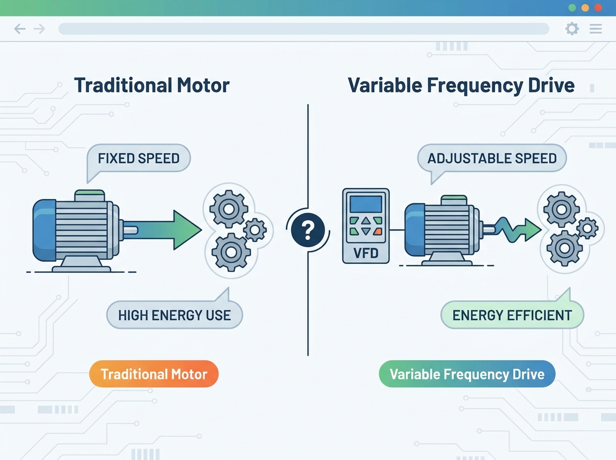
Industrial facilities and commercial operations face compounding pressure to reduce energy consumption and mechanical wear, forcing a reevaluation of legacy motor control systems. Traditional fixed-speed motors operate on a binary on/off paradigm. This rigid operational style leads to massive energy waste during partial-load conditions, high inrush currents that degrade electrical infrastructure, and excessive mechanical stress on driven equipment. Facilities relying solely on these older methods often experience accelerated equipment degradation and inflated utility bills.
Upgrading to a Variable Frequency Drive offers precise control over motor speed and torque. This transition requires balancing initial capital expenditure against long-term operational savings, structural implementation complexity, and alternative legacy configurations. By understanding the mechanical and electrical differences between these systems, operators can make informed decisions that optimize plant efficiency and extend asset lifecycles.
Energy Optimization: VFDs drastically reduce energy consumption in variable-torque applications (like centrifugal pumps and fans) by aligning motor speed directly with real-time load requirements, often yielding ROI within 12 to 24 months.
Mechanical Longevity: By eliminating the violent inrush currents and mechanical shocks associated with Direct-On-Line (DOL) and traditional starters, VFDs extend the lifecycle of belts, gears, and bearings.
Implementation Trade-offs: VFD adoption introduces new engineering challenges, including harmonic distortion, motor insulation stress, and the need for specialized cooling, which must be mitigated during system design.
Application Specificity: Traditional fixed-speed control remains the most cost-effective and reliable choice for applications requiring continuous 100% speed operation with minimal load variation.
Table of Contents
Toggle
The Mechanics of Motor Control: Traditional vs. Variable Frequency Drive
How Traditional Fixed-Speed Motors Operate
Direct-On-Line (DOL) starting represents the most basic method of motor control. When an operator engages a DOL starter, the system connects the AC motor directly to the power supply. This applies full voltage and frequency instantaneously across the motor terminals. The motor accelerates to its rated speed as quickly as the load inertia allows, generating maximum starting torque but also drawing massive electrical current. In field applications, you will hear the aggressive mechanical slam of the contactor pulling in, followed by the immediate strain on the belts or couplings as the motor attempts to reach synchronous speed in a fraction of a second.
Legacy alternative starters attempt to mitigate the harshness of DOL starting. Star-Delta (Wye-Delta) and Auto-transformer starters step down the voltage during the initial startup phase. This reduction lowers the initial torque and current, easing the strain on the electrical supply. However, once the motor reaches its operating speed, these electromechanical methods switch to full voltage. They fail to provide any speed control during normal operation, leaving the motor running constantly at maximum capacity regardless of actual demand. You still end up with a system that only knows how to run flat-out.
The electrical surge during startup presents a significant challenge. A standard DOL start typically draws an inrush current six to eight times higher than the motor's full-load current. This massive draw can cause severe voltage sags across the local power grid, potentially disrupting sensitive electronic equipment nearby. Utilities often monitor these peak demands and apply hefty demand charges, significantly increasing operational expenses for facilities with frequent motor starts. If you have a 200-horsepower motor starting across the line, the lights in the facility will literally dim, and the utility meter will register a massive spike that you pay for all month.
To manage flow or output in traditional systems, operators rely on restrictive mechanical devices. Valves, dampers, louvers, and bypass loops physically throttle the output while the motor continues running at constant maximum speed. This approach is akin to driving a vehicle with the accelerator pressed to the floor while using the brakes to control speed. It represents a pure energy loss, converting wasted mechanical effort into heat and vibration. You are paying for the electricity to generate pressure, and then paying again in mechanical wear to restrict that exact same pressure.
How a Variable Frequency Drive Operates
Modern motor control relies on sophisticated power electronics. The core components of a drive system work in stages to manipulate the incoming power. First, the rectifier section converts the incoming alternating current (AC) from the utility grid into direct current (DC). Next, the DC bus, consisting of large capacitors and inductors, smooths and stores this DC power, filtering out ripples. Finally, the inverter stage utilizes Insulated-Gate Bipolar Transistors (IGBTs) to rapidly switch the DC power on and off. This technique, known as Pulse Width Modulation (PWM), creates a simulated AC output waveform that the motor interprets as a clean power supply.
Drive technologies fall into specific topology classifications based on their internal design. Understanding these differences dictates which unit you specify for a given application:
Voltage Source Inverters (VSI): The most common modern type, storing energy in capacitors on the DC bus. They offer excellent speed control and are highly efficient for standard industrial applications like pumps, fans, and conveyors.
Current Source Inverters (CSI): Utilizing large inductive chokes in the DC link instead of capacitors. Engineers typically specify CSIs for large medium-voltage applications requiring inherent short-circuit protection and regenerative capabilities.
Load Commutated Inverters (LCI): Designed specifically for high-power, high-speed synchronous motor control, often found in massive compressor or blower applications in petrochemical plants.
The fundamental principle of these drives lies in voltage and frequency modulation. Adjusting the frequency (measured in Hertz) directly dictates the rotational speed (RPM) of the connected AC motor. Simultaneously, the drive adjusts the output voltage to maintain an optimal Volts-per-Hertz (V/Hz) ratio. Maintaining this ratio ensures the motor produces consistent, reliable torque across its entire speed range without overheating. If you drop the frequency to 30Hz but leave the voltage at 480V, the motor will saturate and burn up. The drive handles this balancing act automatically.
Industry terminology often causes confusion between a Variable Frequency Drive and a Variable Speed Drive (VSD). While all VFDs function as VSDs by controlling AC motors via frequency variation, VSD is a broader category. The VSD umbrella also includes DC drives, which control DC motors by altering voltage, as well as mechanical variable speed pulleys and hydraulic fluid couplings. When you specify equipment, you must be exact with your terminology to avoid receiving a mechanical variator when you needed a solid-state electronic controller.
Core Evaluation Dimensions: Features to Operational Outcomes
Energy Consumption and Efficiency Gains
The most compelling argument for modern motor control lies in the Affinity Laws. These mathematical principles govern centrifugal applications, such as pumps and fans. According to the Affinity Laws, the power consumption of a centrifugal load is proportional to the cube of the motor speed. Therefore, a relatively small reduction in speed yields a massive reduction in energy use. Operating a fan at 80% speed requires only about 51% of the power needed for full-speed operation. If you drop that speed to 50%, you are only using 12.5% of the rated power. This non-linear relationship is where the massive energy savings originate.
Eliminating mechanical throttling transforms system efficiency. Running a traditional motor at full speed against a partially closed valve forces the pump to work against artificial resistance, wasting immense amounts of energy. Dynamically slowing down the motor to match the exact flow requirement eliminates this artificial resistance. The energy savings achieved by removing mechanical dampers and valves often justify the equipment upgrade within the first year of operation. You stop fighting your own piping system and start delivering exactly the fluid volume the process demands.
Mechanical Stress and Equipment Lifespan
Programmable acceleration and deceleration ramps fundamentally change how equipment starts and stops. Soft starting prevents the violent mechanical shocks and torsional stresses inherent to direct-on-line startups. In fluid systems, this controlled ramp-up eliminates water hammer—a destructive pressure surge that can rupture pipes, blow out gaskets, and damage check valves. Gradual deceleration provides similar benefits, allowing heavy inertial loads to coast down smoothly without stressing braking components or causing fluid column separation in vertical piping runs.
Reducing mechanical fatigue directly extends asset lifecycles. Traditional rigid starts stretch belts, shear coupling keys, and prematurely wear out motor bearings. By applying torque smoothly, modern drives drastically reduce the wear and tear on all downstream mechanical components. This reduction in physical stress translates directly into extended maintenance intervals, fewer emergency repairs, and longer operational life for the entire driven system. You spend less time replacing sheared pins and more time actually running production.
Process Control and Precision
Dynamic load matching allows facilities to achieve unprecedented process stability. Modern drives integrate seamlessly with Programmable Logic Controllers (PLCs) and field sensors monitoring pressure, flow, or temperature. Through automated, real-time closed-loop process optimization (such as PID control), the drive continuously adjusts motor speed to maintain exact setpoints. This eliminates the sluggish response and inherent inaccuracy of mechanical control loops. If a pressure transducer detects a 2 PSI drop, the drive ramps up the motor by a few Hertz instantly to compensate, maintaining a perfectly flat pressure curve.
Torque response varies significantly based on the chosen control method. Traditional starters offer zero torque control during operation. Advanced drives utilize various algorithms to manage torque based on the application requirements:
Scalar (V/Hz) Control: Works well for simple variable-torque loads like fans and centrifugal pumps where precise speed regulation is not critical.
Open-Loop Vector Control: Provides tighter speed regulation and higher starting torque for demanding applications like conveyors or extruders, calculating motor slip without a physical encoder.
Closed-Loop Field-Oriented Control: Utilizes physical encoder feedback mounted on the motor shaft to deliver absolute precision, holding full torque even at zero speed for critical positioning tasks like hoists or cranes.
System Configuration Architectures: Single VFD vs. Twin (Duplex) Systems
Dual-Drive and Redundant Layouts
Complex industrial processes often require specialized architectures, such as Twin or duplex drive systems. In a Twin configuration, two parallel drives manage two separate motors, or occasionally share the load of a single massive system, in a highly coordinated fashion. This architecture departs from the standard single-drive setup, offering distinct operational advantages for critical infrastructure like municipal water pumping stations or hospital chiller plants.
Twin setups frequently utilize lead-lag scheduling. The control system automatically rotates operational hours between the two motors. This master-slave control strategy prevents uneven wear, ensuring both pump or fan assemblies age at the same rate. During periods of low demand, the system can run entirely on a single drive, optimizing efficiency. When demand spikes, the lag drive automatically kicks in to provide supplemental power. You program the PLC to swap the lead drive every 168 hours (one week) to keep the bearing grease distributed and the motor windings dry.
Redundancy represents the primary benefit of duplex systems. A Twin configuration severely mitigates the risk of catastrophic facility failure. If one drive or motor experiences a fault, critical industrial processes and HVAC systems can continue operating at 50% capacity. This duty cycle benefit prevents total shutdowns in environments where continuous operation is mandatory, such as data center cooling loops or continuous manufacturing lines. You never want to be in a situation where a single blown fuse takes down an entire production facility.
Evaluating duplex systems requires weighing higher initial hardware and engineering costs against long-term operational resilience. The upfront capital required for two drives, dual motor wiring, and complex integration logic is substantial. However, facilities offset these costs through drastically reduced maintenance downtime and the elimination of total production halts caused by single-point failures. When you factor in the cost of lost production per hour, the second drive often pays for itself the first time the primary drive trips out on an overvoltage fault.
Comparison: Single Drive vs. Twin (Duplex) Configuration
Feature
Single Drive Architecture
Twin (Duplex) Architecture
Initial Hardware Investment
Lower
Higher
System Redundancy
None (Single point of failure)
High (N+1 capability)
Wear Distribution
Concentrated on one motor
Evenly distributed via Lead-Lag
Maintenance Downtime
Requires full system shutdown
Allows partial operation during service
Space Requirements
Minimal footprint
Requires larger electrical enclosures
Financial Analysis and Operational ROI
Upfront Costs vs. Long-Term Savings
Procuring traditional motor starters and contactors requires minimal initial investment. These electromechanical devices are simple, mass-produced, and easy to install. Conversely, upgrading to advanced motor control hardware demands a higher initial capital expenditure. Facilities must budget for the drive units themselves, specialized shielded cabling to prevent electromagnetic interference, and potentially upgraded cooling systems for the electrical rooms housing the equipment. You also have to account for the specialized labor required to program the parameters and tune the PID loops.
Calculating the payback period requires a detailed analysis of local utility rates, operating hours, and specific load profiles. Facilities must measure the current energy draw of the mechanically throttled system and compare it to the projected energy use under variable speed control. In applications running 24/7 with fluctuating demand, the energy savings often cover the initial equipment and installation costs within a highly favorable timeframe. If you have a 100HP cooling tower fan that only needs to run at 60% speed at night, the kilowatt-hour reduction is massive.
Maintenance and Downtime Considerations
Traditional contactors are rugged and require minimal routine maintenance beyond occasional visual inspections for pitted contacts or loose lugs. Modern drives, being complex electronic devices, require strict preventative maintenance schedules. Technicians must regularly clean cooling fans, inspect DC bus capacitors for bulging or leaking electrolyte, monitor bus voltage, and perform firmware updates to ensure optimal performance and security. If you let dust build up on the IGBT heat sinks, the drive will derate itself and eventually trip on an over-temperature fault.
The true financial impact often lies in the cost of downtime. Unexpected mechanical failures in traditional systems result in sudden, catastrophic halts to production. Modern control systems provide extensive diagnostic capabilities, prognostic fault logging, and built-in protective features against overvoltage, undervoltage, and ground faults. These diagnostics allow maintenance teams to identify and resolve issues before they cause unplanned outages, protecting facility output. Instead of guessing why a motor tripped, you pull the fault history and see exactly what the current and voltage were at the millisecond of the event.
Utility Rebates and Compliance Standards
Energy efficiency incentives significantly alter the financial equation. Many local utilities and government bodies offer substantial rebates to facilities that upgrade their motor control systems. These financial incentives are designed to reduce overall strain on the regional power grid. Securing these rebates often requires baseline energy audits and post-installation verification. You usually have to install temporary power loggers on the existing DOL setup for a week, then log the new setup to prove the kilowatt reduction to the utility company.
Meeting stringent energy efficiency mandates is no longer optional for many operations. Standards set by organizations like Natural Resources Canada and the Department of Energy dictate minimum efficiency levels for industrial equipment. Upgrading to intelligent motor control helps facilities maintain compliance with these evolving regulations, avoiding potential fines and ensuring long-term operational viability. Building codes are increasingly requiring variable speed control on any HVAC motor over 5 horsepower.
Implementation Realities and Adoption Risks
Harmonic Distortion and Power Quality
The non-linear load profile of modern power electronics introduces harmonic distortion back into the facility's electrical grid. Because the rectifier stage draws current in short, rapid pulses rather than a smooth sine wave, it distorts the incoming voltage waveform. If left unmanaged, severe harmonic distortion can overheat distribution transformers, cause nuisance tripping of circuit breakers, and interfere with sensitive communication networks across the plant. You will start seeing random PLC communication drops and flickering LED lights on the same electrical bus.
Mitigating these power quality issues requires proactive engineering. System designers must incorporate line reactors or DC chokes to smooth the current draw. In larger installations, passive or active harmonic filters become necessary to cancel out specific harmonic frequencies. Facilities must ensure their installations comply with strict power quality standards, such as IEEE 519, to protect their internal grid and maintain good standing with the local utility provider. An active harmonic filter acts like noise-canceling headphones for your electrical system, injecting inverse currents to flatten the waveform.
Motor Insulation Stress and Bearing Currents
High-frequency PWM switching creates rapid voltage rise times (dV/dt). These fast transitions can cause voltage spikes, known as reflected waves, to travel down the motor cables. If the cable run is long, these spikes can amplify, subjecting the motor windings to voltages far exceeding their design limits. This stress rapidly degrades standard motor insulation, eventually leading to a short circuit. Mitigating this risk necessitates the use of specialized inverter-duty motors equipped with robust insulation systems capable of handling 1600V spikes.
Common-mode voltage presents another significant risk to motor longevity. The switching action of the inverter can induce stray high-frequency currents on the motor shaft. These currents seek the path of least resistance to ground, which is often through the motor bearings. As the current arcs across the microscopic gap in the bearing lubricant, it causes fluting and pitting on the bearing races. Engineers prevent this premature bearing failure by installing shaft grounding rings, carbon brushes, or electrically insulated bearings. If you hear a high-pitched whining noise coming from a motor bearing that was installed three months ago, you likely have a fluting problem.
Environmental and Cooling Requirements
Thermal management is critical for the reliable operation of power electronics. The conversion of AC to DC and back to AC is not perfectly efficient; a small percentage of the power is lost as heat. In large industrial drives, this heat generation is substantial. Electrical enclosures must be adequately sized and equipped with filtered ventilation fans or dedicated air conditioning units to keep internal temperatures within safe operating limits. You cannot just stuff a 100HP drive into a sealed metal box in a 100-degree boiler room and expect it to survive.
Environmental contaminants pose a severe threat to exposed circuit boards. Dust, moisture, and corrosive gases can cause short circuits and premature failure of the drive components. Facilities must select the appropriate enclosure rating (such as NEMA 12 for dusty environments or NEMA 4X for washdown areas) to protect the sensitive electronics. Proper placement, away from direct heat sources and excessive vibration, further ensures the long-term stability of the installation. Conformal coating on the circuit boards is a mandatory specification if you are installing the unit in a wastewater treatment plant with high hydrogen sulfide levels.
Conclusion
Audit your facility's motor inventory to identify centrifugal pumps and fans currently utilizing mechanical throttling valves or dampers for flow control.
Install power quality loggers on the main electrical service to establish a baseline and determine if harmonic mitigation equipment will be required before adding non-linear loads.
Specify inverter-duty motors equipped with shaft grounding rings for all new installations to prevent insulation breakdown and bearing fluting.
Establish a strict preventative maintenance schedule focused on cleaning heat sinks, replacing enclosure air filters, and verifying cooling fan operation.
FAQ
Q: Can a standard AC motor be used with modern variable frequency control?
A: While standard motors can operate on these drives, it is not recommended for long-term reliability. The high-frequency switching causes voltage spikes that degrade standard insulation. Inverter-duty motors, which feature reinforced winding insulation and often include bearing protection, should be used to prevent premature failure.
Q: How do these drives save energy in pump applications?
A: They save energy by adhering to the Affinity Laws. Instead of running a pump at full speed and restricting the flow with a valve, the drive slows the motor down to match the exact flow required. Because power consumption drops at the cube of the speed reduction, massive energy savings occur.
Q: What is the difference between a VFD and a soft starter?
A: A soft starter only controls the voltage during the initial startup and shutdown phases to prevent mechanical shock and electrical inrush. Once the motor is running, it operates at full fixed speed. A drive controls both voltage and frequency, allowing for continuous speed adjustment during normal operation.
Q: Why do I need a line reactor with my installation?
A: Line reactors act as a buffer between the drive and the power grid. They absorb voltage transients and power line spikes, protecting the sensitive electronics inside the drive. Additionally, they help reduce the harmonic distortion that the drive pushes back into the facility's electrical system.
Q: What causes bearing fluting in motor applications?
A: Bearing fluting is caused by common-mode voltage generated by the drive's rapid switching. This induces a voltage on the motor shaft. When the voltage exceeds the dielectric strength of the bearing grease, it arcs through the bearings to ground, creating microscopic pits that eventually destroy the bearing.
Q: How far can the motor be installed from the drive unit?
A: Cable length limits depend on the drive manufacturer and the motor's insulation rating. Long cable runs amplify reflected wave voltage spikes. Generally, runs over 100 feet require a dV/dt filter or a sine wave filter at the drive output to protect the motor windings from high-voltage transients.