You are here: Home » Blogs » Troubleshooting Common Issues with Variable Frequency Drives: A Guide
Troubleshooting Common Issues with Variable Frequency Drives: A Guide
Views: 0 Author: Site Editor Publish Time: 2026-07-21 Origin: Site
Unplanned downtime caused by motor control failures directly impacts production yields and operational overhead. When a drive trips, maintenance teams often misdiagnose the root cause, leading to unnecessary equipment replacement. The challenge lies in isolating whether the fault is internal to the hardware or a symptom of external system degradation, such as cabling issues, motor health, or power supply fluctuations. This guide provides a systematic framework for diagnosing common Variable Frequency Drive issues, resolving persistent fault codes, and determining the threshold for repairing versus replacing the unit. By following these steps, you can accurately identify the source of the problem and implement effective solutions on the plant floor without relying on guesswork.
External vs. Internal: Over 80% of drive faults originate outside the unit itself, typically stemming from undersized specifications, installation defects, or motor degradation.
Systematic Diagnostics: Effective troubleshooting requires isolating the power supply, the drive, the cabling, and the motor to prevent recurring alarm codes.
Parameter Adjustments: Many nuisance trips can be resolved through precise parameter tuning, such as lowering carrier frequencies or adjusting deceleration times, before physical repairs are necessary.
Repair vs. Replace: The decision to replace a drive should be based on a strict cost-benefit analysis involving the unit's lifecycle stage, capacitor health, and the availability of OEM replacement parts.
Table of Contents
Toggle
The Baseline: Differentiating Internal vs. External Variable Frequency Drive Faults
Why Most Faults Originate Outside the Drive
A common misconception on the factory floor is that a drive fault code automatically indicates a broken drive. In reality, the drive acts as a highly sensitive system sensor. It trips to protect itself and the connected motor from external anomalies. These anomalies frequently include supply voltage spikes, mechanical binding in the load, or degraded motor insulation. When the drive detects conditions outside its safe operating parameters, it shuts down to prevent catastrophic damage. Replacing the drive without investigating the mechanical load or power quality usually results in the new unit tripping with the exact same fault code.
Consider the operating environment. High ambient temperatures, excessive dust, and poor power quality from the utility grid all contribute to system instability. A drive might log an overvoltage fault, but the root cause could be a utility capacitor bank switching on miles away. Understanding that the drive is often the messenger, rather than the source of the problem, is the first step in effective troubleshooting.
The baseline for a successful diagnostic process is identifying the true root cause rather than merely resetting the fault. Hitting the reset button without investigating the underlying issue often leads to recurring trips, degraded components, and eventual catastrophic failure. You need the right tools for the job. Essential diagnostic equipment includes a high-quality digital multimeter with a reliable diode-check function, a true-RMS clamp meter for accurate current readings, and an insulation resistance tester (Megger) for checking motor windings and cables.
Safety parameters for testing are non-negotiable. Always verify a zero energy state and ensure strict lockout/tagout (LOTO) verification is complete before opening any enclosure. DC bus capacitors store lethal amounts of energy long after the input power is removed. You must allow these capacitors to fully discharge according to the manufacturer's specified time. Always measure the DC bus voltage across the positive and negative terminals to ensure it is below 50VDC before touching any internal components.
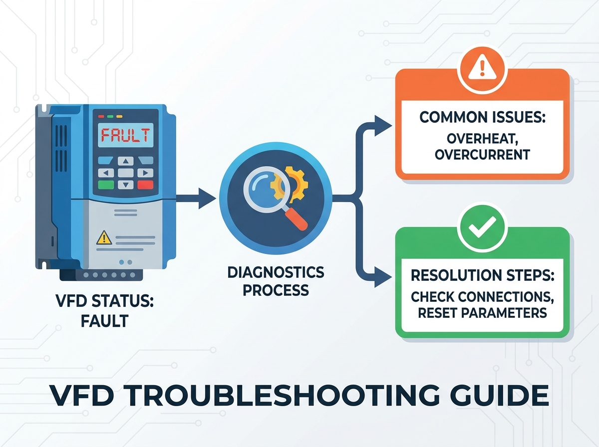
The Master VFD Troubleshooting Flowchart (Step-by-Step Diagnostic Sequence)
Follow this sequential checklist to systematically diagnose drive issues and eliminate variables one by one:
Visual & Sensory Inspection: Look for burnt smells, corrosion on control boards, blocked cooling fans, or loose terminal connections. Many failures are visible to the naked eye.
Input Power Check: Verify voltage balance across all three phases. Check for phase loss or severe voltage sags on the incoming power supply using your true-RMS meter.
Static Testing: Perform diode and IGBT checks using a multimeter to verify the integrity of the power section before applying any voltage.
Output & Cable Checks: Conduct insulation testing on the motor cables and windings to rule out ground faults or phase-to-phase shorts.
Dynamic Testing: If safe to do so, compare an unloaded motor run with a loaded run to isolate mechanical binding from electrical faults.
Diagnostic Step
Tool Required
Expected Outcome
Action if Failed
Input Voltage Check
True-RMS Multimeter
Balanced 3-phase voltage within 10% of rating
Investigate utility supply, fuses, or breakers.
Static Diode Check
Multimeter (Diode Mode)
0.3V to 0.6V forward bias, OL reverse bias
Replace drive or rectifier module if shorted.
Motor Insulation Test
Megger (500V/1000V)
> 100 Megohms to ground
Repair or replace motor/cabling. Do not run drive.
Diagnosing Common Variable Frequency Drive Alarm Codes
Overcurrent and High Starting-Current Faults
Overcurrent faults are among the most frequent nuisance trips and often point directly to physical causes on the machine. Mechanical overload, a locked rotor, or a failing motor bearing will force the motor to draw excessive current, tripping the drive. Electrical causes include short circuits in the motor cable, phase-to-phase shorts within the motor windings, or grounded outputs. You must isolate the motor from the drive to determine if the short is in the wiring or the drive's output section.
Parameter settings frequently trigger overcurrent faults during commissioning or after a process change. If the acceleration time is set too short for a high-inertia load, the drive will push maximum current trying to reach the target speed, hitting the hardware current limit. Incorrect V/Hz curve settings can also over-flux the motor, leading to massive current spikes during startup. Adjusting the acceleration ramp or switching to a sensorless vector control mode can often resolve these issues without turning a single wrench.
Overvoltage and Undervoltage Trips
Overvoltage during deceleration typically occurs when the load inertia drives the motor faster than the programmed deceleration time. The motor acts as a generator, pushing energy back into the drive and raising the DC bus voltage until the high-voltage limit is breached. Mitigation strategies include installing dynamic braking resistors to burn off the excess energy as heat, or simply extending the deceleration ramp to match the natural coasting time of the load.
Undervoltage trips are usually external. They stem from utility power sags, loose input terminal connections, or blown input fuses causing a single-phase condition. If a facility experiences heavy machinery starting up on the same electrical bus, the resulting voltage drop can easily trigger an undervoltage fault on sensitive drives. Installing line reactors can help buffer the drive from these transient voltage sags.
Overheating and Thermal Overload
You must differentiate between drive over-temperature and motor thermal overload. Drive over-temperature is a hardware protection mechanism. It is often caused by clogged heat sinks, failed internal cooling fans, or ambient temperatures exceeding the enclosure's rating. Regular cleaning of the heat sinks and verifying fan operation are mandatory maintenance tasks.
Motor thermal overload, on the other hand, is a calculated fault based on the current draw and operating speed. It typically occurs when running a standard induction motor at low speeds for extended periods. The motor's internal cooling fan loses efficiency at low RPMs, causing heat to build up even if the current is within nameplate limits. Address this by installing auxiliary cooling fans on the motor or adjusting the drive's thermal overload parameters to match the specific motor class.
Component-Level Troubleshooting and Technical Fixes
Static Power Section Testing: Checking Rectifiers and IGBTs
Before applying power to a suspect drive, perform a static diode check on the input rectifier bridge. Use a multimeter set to the diode function. Place the positive lead on the negative DC bus terminal and probe the incoming phases (L1, L2, L3) with the negative lead. You should see a standard diode drop (usually 0.3V to 0.6V). Reverse the leads to check for an open circuit (OL). Repeat this process for the positive DC bus terminal. A shorted reading (0.0V) indicates a blown rectifier.
Similarly, perform a static test on the output Insulated-Gate Bipolar Transistors (IGBTs). Probe between the DC bus terminals and the output motor terminals (T1, T2, T3). Interpreting these multimeter readings helps pinpoint internal component failures prior to applying power. If an IGBT is shorted, applying power will likely cause a catastrophic failure, potentially damaging the control board and surrounding components.
Inspecting Capacitors and DC Bus Health
DC bus capacitors smooth the rectified voltage and provide the necessary energy storage for the inverter section. Their typical lifespan is 7 to 10 years, heavily dependent on usage, ambient temperature, and power quality. Symptoms of capacitor degradation include physical bulging, leaking electrolyte, or frequent, unexplained undervoltage or DC ripple faults.
To assess capacitor health, measure the DC bus voltage while the drive is running under load. The DC bus voltage should be approximately 1.414 times the AC input voltage (e.g., around 680VDC for a 480VAC system). Significant voltage ripple or a lower-than-expected DC bus voltage indicates failing capacitors. In many modern drives, the capacitors are integrated into the power module, requiring a complete module replacement if they fail.
Motor Degradation and Cable Insulation Testing
Degraded cable insulation or failing motor windings cause intermittent ground faults that are notoriously difficult to track down. These faults often present as nuisance trips that disappear when the drive is reset, only to return hours or days later. Standard multimeters cannot detect these high-voltage insulation breakdowns.
You must use a Megger to test the insulation resistance. Crucially, always disconnect the motor leads from the drive before performing a Megger test. The high voltage generated by the insulation tester (typically 500V or 1000V) will destroy the drive's sensitive output IGBTs and control electronics. Test phase-to-phase and phase-to-ground. Readings below 100 Megohms generally indicate moisture ingress or insulation degradation requiring motor repair or cable replacement.
Adjusting Carrier Frequencies for Stability
The carrier frequency (or switching frequency) determines how fast the output IGBTs turn on and off to simulate the AC sine wave. Factory defaults are usually set between 4 kHz and 8 kHz. Lowering the carrier frequency to 2.5 kHz or 3 kHz can alleviate several field issues. It significantly reduces capacitive cable charging currents on long motor leads, which can cause nuisance overcurrent trips.
Lowering the switching frequency also reduces the switching losses within the IGBTs, lowering the drive's overall operating temperature. However, this adjustment comes with a trade-off: it increases the audible magnetic whine produced by the motor. In industrial environments, this noise is rarely an issue, making carrier frequency reduction a highly effective, zero-cost troubleshooting step for stability issues.
Controller and Interconnection Diagnostics
Communication and control wiring issues often masquerade as drive failures. A lost 4-20mA speed reference signal, loose terminal blocks, or a failing start/stop relay will halt operation without necessarily generating a specific fault code. EMI/RFI interference on control cables is another common culprit, causing erratic speed fluctuations or random stops.
Verify shielding and grounding protocols to eliminate noise-induced issues. Ensure that low-voltage control cables are routed in separate conduits from high-voltage power cables. Control cable shields must be grounded at one end only (typically at the drive chassis) to prevent ground loops. Inspect all terminal connections for tightness and corrosion, as industrial vibration frequently loosens control wiring over time.
The Repair vs. Replace Decision Framework
Assessing the Age and Lifecycle of the Variable Frequency Drive
When a drive suffers a hard internal failure, you must evaluate the unit's current position in the OEM lifecycle. Manufacturers classify drives as Active, Legacy, or Obsolete. Maintaining obsolete drives carries significant hidden costs. Replacement parts become scarce and expensive, and firmware support ceases.
If a drive is obsolete, repairing it is often a temporary patch. You risk another component failing shortly after the repair. Upgrading to a current, active model ensures long-term support, access to modern communication protocols, and readily available replacement parts, minimizing future downtime.
Cost-Benefit Analysis of Component Replacement
Apply the standard 50% rule: if the total cost of repair—including parts, labor, shipping, and the cost of extended downtime—exceeds 50% of a new unit's purchase price, replacement is generally the correct financial decision. Replacing modular components like cooling fans, keypads, and control boards is often viable and cost-effective.
However, replacing potted power modules or main rectifier blocks in smaller drives (under 50 HP) is rarely economical. The labor involved in tearing down the drive, cleaning thermal paste, and rebuilding the unit often exceeds the cost of a brand-new drive with a full factory warranty. Always factor in the warranty period of the repair versus a new unit.
Evaluating Undersized Specifications and Scalability
Determine if the current drive is undersized for the application. Chronic overcurrent faults, frequent overheating, and shortened component lifespans are classic signs of an undersized drive. If the mechanical load has increased over the years due to process changes, the original drive may no longer be adequate.
Frame a replacement not just as a maintenance fix, but as an engineering upgrade. A new drive offers the opportunity to specify a unit with higher overload ratings (Heavy Duty vs. Normal Duty), integrated safety features like Safe Torque Off (STO), and native Ethernet communication, improving overall system scalability and safety.
Mitigating Future Failures: Installation and Maintenance Realities
Correcting Installation Defects and Protecting Components
Many drive failures are traced back to day-one installation errors. Improper grounding is a primary cause of erratic behavior and communication faults. Ensure the drive is grounded directly to the main panel ground bus, not daisy-chained through other equipment. Inadequate enclosure ratings for the environment (e.g., using a NEMA 1 drive in a dusty NEMA 12 environment) guarantee premature failure due to contamination.
Apply Line Reactors on the input side to protect the drive's rectifier section from supply voltage transients, surges, and harmonic distortion. On the output side, use Load Reactors or dV/dt Filters to mitigate the reflective wave phenomenon (voltage spikes) that occurs on long motor lead lengths (typically those over 100 feet). These passive components significantly extend the life of both the drive and the motor.
Establishing a Preventative Maintenance Baseline
Reactive maintenance is expensive. Outline a realistic preventative maintenance schedule based on the operating environment. This schedule must include routine visual inspections for dust buildup and corrosion. Use thermal imaging cameras to scan power connections under load; a hot connection indicates high resistance and impending failure.
Establish strict fan replacement intervals. Cooling fans have mechanical bearings that wear out; replace them every 3 to 5 years regardless of apparent condition. Finally, maintain regular parameter backups. Having a verified backup file allows a technician to program a replacement drive in minutes rather than spending hours manually entering parameters from a printed manual.
Conclusion
Effective troubleshooting requires looking beyond the keypad and analyzing the entire electromechanical system. When internal hardware failure is confirmed, weigh the immediate cost of repair against the long-term reliability and warranty of a modern replacement. A systematic approach prevents parts-changing and ensures maximum uptime.
Document all baseline parameters and save them to a secure network location for rapid deployment during a failure.
Conduct a thorough system audit, including motor insulation testing, cable routing checks, and power quality analysis.
Consult with a certified integration or repair partner for units nearing the end of their lifecycle to plan migration paths.
Implement a strict preventative maintenance schedule focusing on thermal management and connection integrity.
FAQ
Q: What is the most common cause of a Variable Frequency Drive fault?
A: Most faults originate from external issues such as mechanical binding, undersized drive specifications, or power supply fluctuations, rather than internal drive failure.
Q: How do I fix an overcurrent fault on my VFD?
A: Check for mechanical jams, verify motor wiring for shorts, and ensure the acceleration time is not too short for the load inertia.
Q: Why does my VFD trip on overvoltage during deceleration?
A: The load is regenerating power back into the drive. Fix this by extending the deceleration time or adding a dynamic braking resistor.
Q: How do I safely perform a static check on a VFD using a multimeter?
A: Isolate input power, verify safe discharge of the DC bus, then use the diode-check mode to test the forward and reverse bias of the input rectifier diodes and output IGBTs.
Q: Can a bad motor ruin a Variable Frequency Drive?
A: Yes. A motor with shorted windings can cause severe overcurrent spikes that may eventually damage the drive's insulated-gate bipolar transistors (IGBTs).
Q: How often should VFD capacitors be replaced?
A: Typically every 7 to 10 years, though high ambient temperatures and heavy usage can shorten this lifespan significantly.
Q: When should I replace rather than repair my VFD?
A: Replace when the unit is obsolete, when repair costs exceed 50% of a new unit, or when the application requires features the current drive lacks.