You are here: Home » Blogs » Top 5 Specifications to Consider When Buying a Variable Frequency Drive
Top 5 Specifications to Consider When Buying a Variable Frequency Drive
Views: 0 Author: Site Editor Publish Time: 2026-07-21 Origin: Site
Mis-sizing motor control equipment introduces severe operational and financial risks to any facility. When you install the wrong drive, you face premature motor failure, excessive harmonic distortion, and unplanned facility downtime. A frequent procurement mistake involves selecting a drive based solely on horsepower. This approach completely ignores critical variables like load dynamics, duty cycle, environmental hazards, and network integration requirements. Relying on horsepower alone often results in underperforming systems and burned-out components.
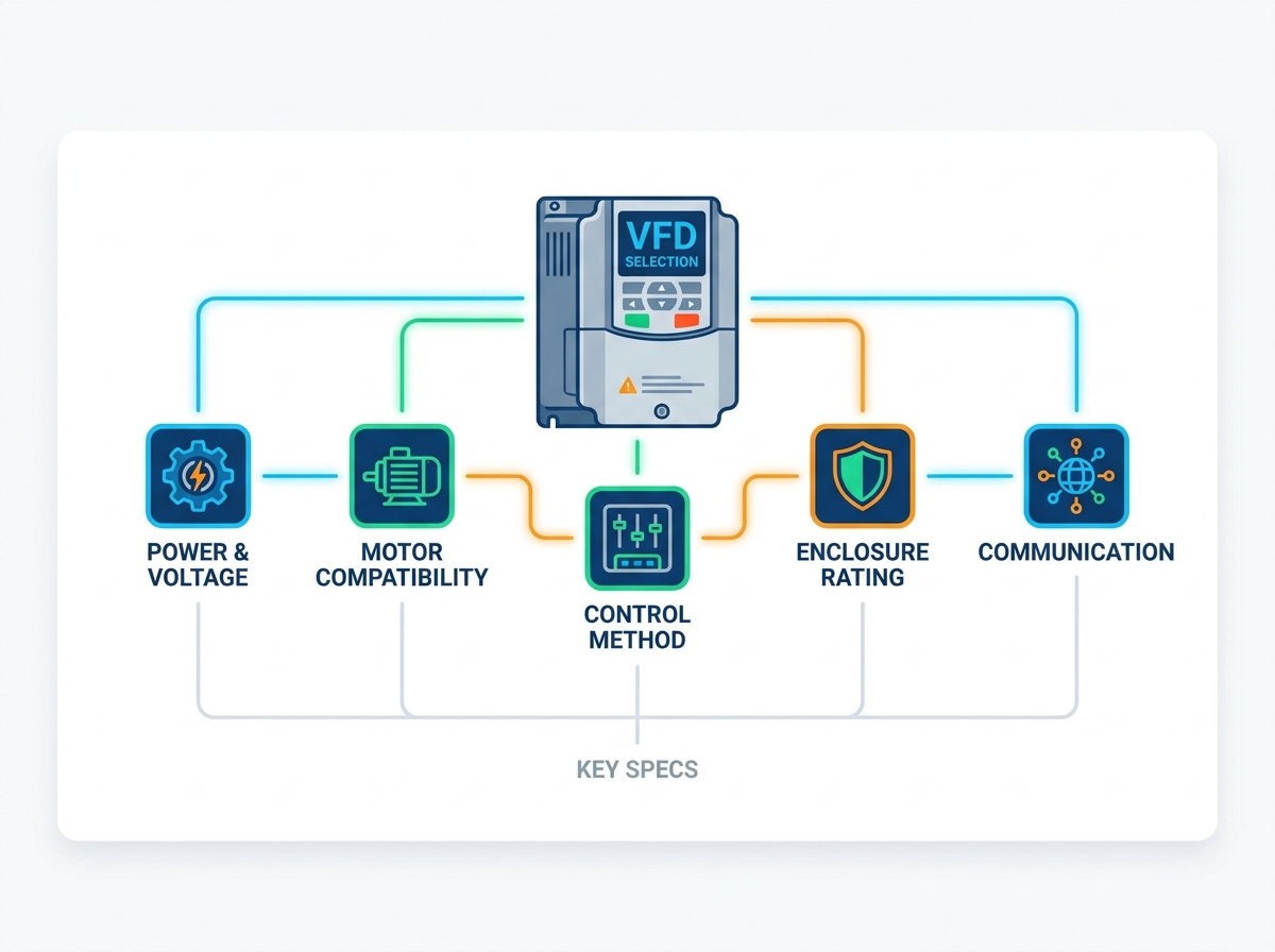
You need a structured evaluation framework based on the most critical technical specifications to prevent these failures. By analyzing the mechanical load, electrical supply, and operating environment, you ensure the selected Variable Frequency Drive aligns with process requirements, facility infrastructure, and long-term reliability goals. The following breakdown details the exact specifications you must evaluate before finalizing your equipment selection.
Always size a drive based on the motor's Full Load Amps (FLA) rather than horsepower to account for operational inefficiencies and voltage fluctuations.
Match the drive's overload capacity and speed regulation capabilities to the specific load profile (constant torque vs. variable torque) and duty cycle.
Internal hardware components, specifically DC bus capacitor types (electrolytic, film-type, or oil-filled) and pre-charge circuitry, dictate the long-term reliability and lifespan of the drive.
Environmental factors dictate the required enclosure rating (NEMA/IP); under-specifying this leads to rapid component degradation from dust, moisture, or heat.
Integration requirements—ranging from basic hardwired I/O to advanced industrial Ethernet protocols and commissioning interfaces—must be defined prior to purchase.
Table of Contents
Toggle
Specification 1: Load Profile, Torque Characteristics, and Duty Cycle
The mechanical realities of your application dictate the success of your installation. The drive must supply adequate current to produce the required torque at all operating speeds without overheating. This becomes especially important under transient load conditions. If you fail to match the drive to the load profile, you guarantee operational instability and frequent nuisance tripping.
Variable Torque vs. Constant Torque
You must classify your load correctly before looking at any other specification. Fans and centrifugal pumps represent variable torque loads. In these applications, torque requirements drop significantly at lower speeds. A standard 110% overload capacity for 60 seconds handles these loads easily. Conversely, conveyors, extruders, and positive displacement pumps act as constant torque loads. They demand consistent torque across the entire speed range. You need 150% to 200% overload capacity for high starting torque and sustained low-speed operation.
Load Type
Application Examples
Torque Characteristic
Required Overload Capacity
Variable Torque
Centrifugal fans, centrifugal pumps, blowers
Torque decreases with the square of the speed
110% for 60 seconds
Constant Torque
Conveyors, extruders, mixers, hoists
Torque remains constant regardless of speed
150% to 200% for 60 seconds
Speed Range, Speed Regulation, and Control Modes
Simple applications rely on V/Hz (Volts per Hertz) control for basic speed regulation. This works fine for a standard ventilation fan. However, applications requiring precise speed regulation and high torque at near-zero speeds demand Sensorless Vector or Closed-Loop Vector control. You must define the required speed turndown ratio. A 10:1 ratio means the motor can run at one-tenth of its base speed. A 1000:1 ratio requires closed-loop encoder feedback to ensure the motor runs slowly without stalling or overheating.
Duty Cycle and Acceleration/Deceleration Dynamics
Highly cyclic or intermittent duty cycles push the thermal limits of the drive hardware. You must specify acceleration and deceleration time requirements accurately based on the process. High-inertia loads, like large centrifuges or flywheels, require rapid deceleration. These applications necessitate dynamic braking resistors or regenerative drives to dissipate excess energy safely. Without braking resistors, the drive will trip on an overvoltage fault during deceleration.
Implementation Risk & Mitigation
Motor overheating at low speeds presents a massive risk in constant torque applications. Standard motors use shaft-mounted fans for cooling. When the motor runs slowly, the fan moves less air, but the motor still generates full heat. Mitigate this by verifying the motor's turndown ratio. You can also utilize an auxiliary blower for force-cooling or select a dedicated inverter-duty motor designed specifically for low-speed thermal management.
Specification 2: Motor Nameplate Data, Electrical Match, and Internal Component Topology
Establishing baseline electrical and hardware requirements prevents immediate commissioning failures. The drive's output must align perfectly with the motor's actual electrical characteristics. Furthermore, the internal design of the unit must match the expected equipment lifecycle of your facility.
Sizing by Full Load Amps (FLA) vs. Horsepower
Horsepower serves as a theoretical mechanical metric. Full Load Amps (FLA) represents the practical electrical metric for drive sizing. You must size the drive based on the motor nameplate FLA. This becomes critical when matching motors of varying efficiency classes or older legacy motors. Motor efficiency and power factor directly impact the actual current draw. Two 50-horsepower motors can have vastly different FLA ratings. Sizing by FLA remains the only reliable method.
Locate the motor nameplate and record the FLA for your specific operating voltage.
Check the drive manufacturer's catalog for the continuous output current rating.
Ensure the drive's continuous output current exceeds the motor's FLA.
Factor in the required overload percentage (110% or 150%) based on the load type.
Input Power Source Characteristics
Match the facility line voltage and frequency precisely to the drive input. Common voltages include 230V, 460V, and 575V. For single-phase to three-phase conversion applications, you must apply a 50% derating rule. When supplying a three-phase motor from a single-phase source, the drive's input rectifiers work twice as hard. You must double the size of the drive to prevent internal component failure.
Internal Hardware and Capacitor Topology (Longevity Factors)
The construction of DC bus capacitors dictates the longevity of the unit. These are the primary wear-and-tear components inside the chassis.
Capacitor Type
Typical Lifespan
Application Suitability
Electrolytic
7–10 years
Standard commercial and light industrial applications. Cost-effective.
Film-Type
10–15 years
Harsh environments with higher ambient temperatures. Enhanced thermal tolerance.
Oil-Filled
20–30 years
Heavy-duty or medium-voltage drives. Maximum reliability for critical infrastructure.
You must also verify the presence of robust pre-charge circuitry. This circuitry uses contactors and resistors, or thyristors, to limit inrush current on power-up. Without a pre-charge circuit, the initial surge of electricity will destroy the DC bus capacitors prematurely.
Overall Value Influencing Factors
Evaluate the trade-off between buying a precisely sized drive versus oversizing by one frame size. Oversizing increases thermal headroom. It helps the unit handle unexpected voltage sags and extends the lifespan of internal components. In heavy industrial environments, oversizing by one frame size often justifies the initial capital investment by preventing early replacement.
Specification 3: Operating Environment, Enclosure Ratings, and Thermal Management
The physical location of the equipment dictates its mechanical protection requirements. Airborne contaminants, ambient temperature, altitude, and moisture destroy drive electronics rapidly. You must specify the correct physical enclosure to protect the internal circuit boards.
NEMA / IP Rating Selection
Selecting the wrong enclosure guarantees a short lifespan for your equipment. NEMA 1 (IP20) enclosures suit clean, climate-controlled electrical rooms or clean motor control center (MCC) cabinets. NEMA 12 (IP54) enclosures are mandatory for typical manufacturing floors. They protect against airborne dust, fibers, and light liquid splashing. NEMA 4/4X (IP66) enclosures are necessary for washdown environments, outdoor installations, or highly corrosive atmospheres like wastewater treatment plants or chemical processing facilities.
Thermal Management, Altitude, and Air Quality
You must derate the drive for high ambient temperatures. Most standard units are rated for 40°C (104°F). If your electrical room hits 50°C, you must oversize the drive to handle the heat. Altitude also plays a major role. Above 1,000 meters (3,300 feet), the air becomes thinner and reduces cooling efficiency. You must derate the output current by roughly 1% for every 100 meters above the 1,000-meter threshold. Account for conductive dusts, such as carbon black or metal shavings, by specifying conformal coating on internal printed circuit boards (PCBs). This coating prevents catastrophic short circuits.
Implementation Risk & Mitigation
Installing standard NEMA 1 drives in unventilated or tightly packed cabinets leads to rapid thermal failure. The drives generate heat, and if that heat cannot escape, the cabinet turns into an oven. Mitigate this by calculating the total heat dissipation (Watts loss) of all components inside the enclosure. Specify appropriate cabinet cooling based on that calculation. You can use passive vents for small loads, forced-air fans for medium loads, or dedicated cabinet air conditioning units for high-heat applications.
Specification 4: Control Logic, Network Communication, and Commissioning Interfaces
The equipment must integrate seamlessly into your existing facility control architecture. Whether you operate the system manually, via a centralized Programmable Logic Controller (PLC), or through a complex industrial network, the control interfaces must match your requirements.
Hardwired I/O Requirements
Evaluate the necessary number of digital inputs and outputs. You need digital inputs for functions like start/stop, reverse, external fault triggers, and multi-speed selection. Determine the required digital or relay outputs for status indication, such as running, faulted, or at-speed signals. You also need analog I/O for speed reference signals (typically 4-20mA or 0-10V) and motor current feedback to your control system.
Count the exact number of digital inputs required for your control scheme.
Verify the voltage level of the digital inputs (24VDC vs. 120VAC).
Ensure enough analog inputs exist for speed reference and PID sensor feedback.
Confirm relay outputs are rated for the voltage and current of your indicator lights or PLC inputs.
Industrial Communication Protocols
Assess compatibility with your facility networks. Common protocols include EtherNet/IP, PROFINET, Modbus TCP/RTU, DeviceNet, or BACnet for HVAC applications. Network integration offers massive operational advantages. It drastically reduces hardwiring, gives you access to advanced diagnostics, enables energy monitoring, and allows for remote parameter configuration from an engineering workstation.
Commissioning, Ease of Operation, and Diagnostics
Compare the usability of the human-machine interface (HMI). Basic LED keypads work for simple setups but make troubleshooting difficult. Multi-language, graphical LCD HMIs provide clear fault descriptions and often include copy-paste functionality. This allows you to program one drive, save the parameters to the keypad, and download them to multiple identical drives on the factory floor. Evaluate the manufacturer’s commissioning software tools for efficient setup, oscilloscope functions, and real-time monitoring.
Evaluation Dimensions (Scalability)
Choose equipment with modular communication cards and expandable I/O options. This scalability allows for future facility network upgrades without requiring the replacement of the entire unit. If your facility transitions from Modbus to EtherNet/IP in five years, you only want to swap a small communication card, not the whole drive.
Specification 5: Power Quality, Harmonic Mitigation, and Output Protection
Variable frequency drives act as non-linear loads. They draw current in short pulses rather than a smooth sine wave. This generates Total Harmonic Distortion (THD) on your electrical grid. This distortion overheats facility transformers, trips circuit breakers, and disrupts sensitive electronics sharing the same power source.
Input-Side Harmonic Mitigation
You must evaluate drives with built-in DC link chokes or specify 3% to 5% AC line reactors. These components limit input-side harmonics and protect the drive's rectifiers from incoming line surges and voltage transients. For larger installations, determine if active front-end (AFE) drives, active harmonic filters, or multi-pulse (12-pulse or 18-pulse) configurations are required to meet IEEE 519 harmonic compliance standards at the utility point of common coupling.
Output Power Quality (Motor & Cable Protection)
Reflected waves (dV/dt) on motor insulation present a massive failure risk. This phenomenon occurs in applications with long motor cable runs, typically over 100 feet (30 meters). The fast switching of the IGBTs inside the drive creates voltage spikes that reflect back and forth along the cable. These spikes can reach twice the DC bus voltage at the motor terminals. Specify output line reactors, dV/dt filters, or sine-wave filters to prevent premature motor winding insulation failure. These filters also reduce bearing pitting caused by common-mode current discharging through the motor bearings.
Measure the exact cable distance between the drive output and the motor terminals.
If the distance exceeds 100 feet, install a 3% output line reactor.
If the distance exceeds 300 feet, install a dV/dt filter.
If the distance exceeds 1000 feet, or if using an older non-inverter duty motor, install a sine-wave filter.
Overall Value Influencing Factors
Weigh the upfront capital cost of harmonic filters, line reactors, and output filters against long-term operational costs. Utility power quality penalties, transformer degradation, and premature motor replacements quickly eclipse the initial savings of omitting these protective components. Doing the engineering upfront saves thousands of dollars in maintenance later.
Conclusion
A successful specification requires a holistic view of the mechanical load, electrical supply, internal hardware design, operating environment, and control system. Focusing on just one aspect leaves your system vulnerable to premature failure.
Build your specification sheet starting with the motor FLA and the specific load type (torque and duty cycle).
Select the internal capacitor design and pre-charge protection based on your required equipment lifespan.
Filter your options by the correct NEMA/IP enclosure rating for your physical environment.
Finalize your selection by defining network communication protocols and necessary harmonic mitigation components.
FAQ
Q: Why should I size a drive based on FLA instead of horsepower?
A: Horsepower is a theoretical mechanical rating. Full Load Amps (FLA) represents the actual electrical current the motor draws. Sizing by FLA accounts for motor efficiency and power factor, ensuring the drive can handle the real electrical load without tripping on overcurrent.
Q: What is the difference between variable torque and constant torque loads?
A: Variable torque loads, like centrifugal fans, require less torque at lower speeds. Constant torque loads, like heavy conveyors, require consistent torque across all speeds. Constant torque applications demand higher overload capacity from the drive to prevent stalling.
Q: How does the operating environment affect drive selection?
A: Dust, moisture, and extreme temperatures degrade electronics rapidly. You must select the appropriate NEMA/IP enclosure rating to block contaminants. You also need to consider conformal coating on circuit boards or specialized cabinet cooling to protect the internal components from heat.
Q: Why are line reactors or harmonic filters necessary?
A: Drives generate harmonic distortion that overheats facility transformers and damages sensitive equipment. Line reactors and harmonic filters mitigate these harmonics, ensuring power quality and maintaining compliance with IEEE 519 utility standards.
Q: What happens if I use a long motor cable without output protection?
A: Long cables create reflected waves (dV/dt) that cause massive voltage spikes at the motor terminals. This leads to rapid breakdown of the motor winding insulation and premature bearing failure due to common-mode currents.